Description / توضیحات
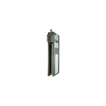
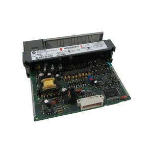
Model 1771-OW16
Output per module 16
Module Location
1771 -A1B thru -A4B I/O Chassis; 1771 -AM1 or AM2
Voltage Rating 24-250V ac (rms), 47-63Hz; 24-150V dc
cos 0.4
Current Rating (maximum per channel)?
0.5A per output at 100V; 0.25A per output at 150V
Minimum Contact Load 10 mA
Operate/Release Time 10ms maximum; 5ms (?1ms) typical
Bounce Time Maximum
4ms
Switching Frequency Maximum
1/3 Hz @maximum load
Expected Life of Electrical Contacts 300K operations @ 25?C (cos 1)
Power Dissipation
All relays off: 0.015 Watts; All relays on: 6.55 Watts
Thermal Dissipation All relays off: 0.05 BTU/hr; All relays on: 22.24 BTU/hr
Backplane Current 1.3A maximum
Maximum Cable Length 1000ft (304.8m)
Isolation Voltage 1500V ac for 1 second customer side to system side;
1500V ac for 1 second channel to channel;
relay rated 4000V coil to contact
Conductors
Wire Size:
Category:
14 gauge (2mm?) stranded maximum?
3/64 inch (1.2mm) insulation maximum
14
Environmental Conditions
Operational Temp.
Storage Temperature
Relative Humidity
0? to 60?C (32? to 140?F)
-40? to 85?C (-40? to 185?F)
5 to 95% (without condensation)
Keying Between 2 and 4
Between 32 and 34
Field Wiring Arm Catalog Number 1771-WN
Wiring Arm Screw Torque 7-9 inch-pounds
Agency Certification (when product or packaging is marked) CSA certified
CSA Class I, Division 2, Groups A, B, C, D certified
UL listed
CE marked for all applicable directives
Installation data 1771-2.206
(1) An individual output should not be subjected to high power loads and then be required to run low power loads.
(2) Output current maximum per module is limited by the maximum output power rating.
(3) 14 gauge wire connected to all terminals may not allow the field wiring arm cover to close. A smaller wire size may be required.
(4) You use this conductor category information for planning conductor routing as described in the system-level installation manual.